I have repaired the sound ribbon cable on my Oculus Rift.
This is not a complete step by step guide and the images may not be in the best order, but it should give you the general idea of how to proceed : )
If you have any idears of your own please post them to help others : )
If you have any parts for sale there is a classified section as well.
Tools Required : -
A soldering iron with a .02mm tip.
Two Tork screwdrivers T2 & T3 and small philips screwdrivers.
My Oculus Rift Headset developed intermittent sound in the left hand earphone.
Pulling the headband nearly fully out would bring back the sound.
A printed cable from the mother board feeds out of the right hand side through the pivot into the headband.
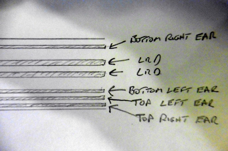
The ribbon proceeds to the right hand earphone, it has six tracks, two split off to that earphone.
Four then proceed further, two to the LEDs at the rear, the remaining two go round to the left side earphone.
A six way flexible cable has to replace the ribbon as far as the right hand earphone from the front section of the headset.
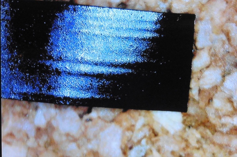
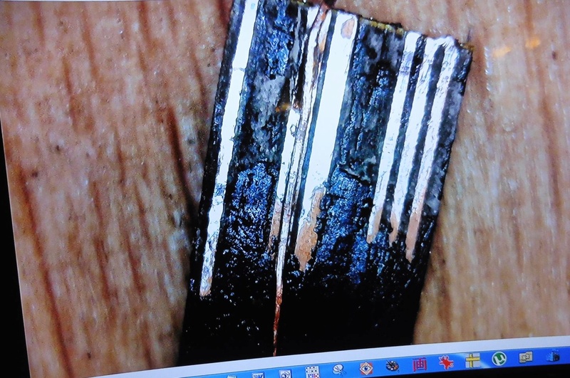
The intermittent break on mine was in the section pictured, I located it using freezer.
Pull the Velcro strip off the right hand side near the pivot.
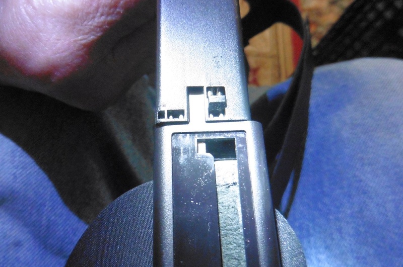
Along this section at the end that the headband slides into, a small plastic wedge can be pushed in, then the headband can be pulled out.
But first remove the small screw inside just before the L/H earphone, the inner side can then be prised out.
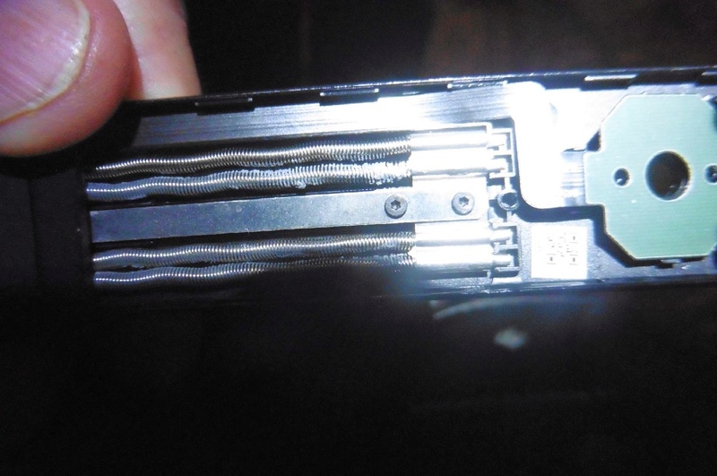
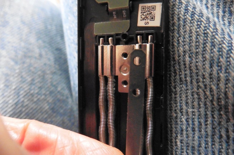
Also the two screws that hold the spring assembly in, see image.
The section of board that the headphone pins make contact with, is stuck to the back with a double sided pad, gently prise it off.
The ribbon should be cut of just before it reaches the earphone pad.
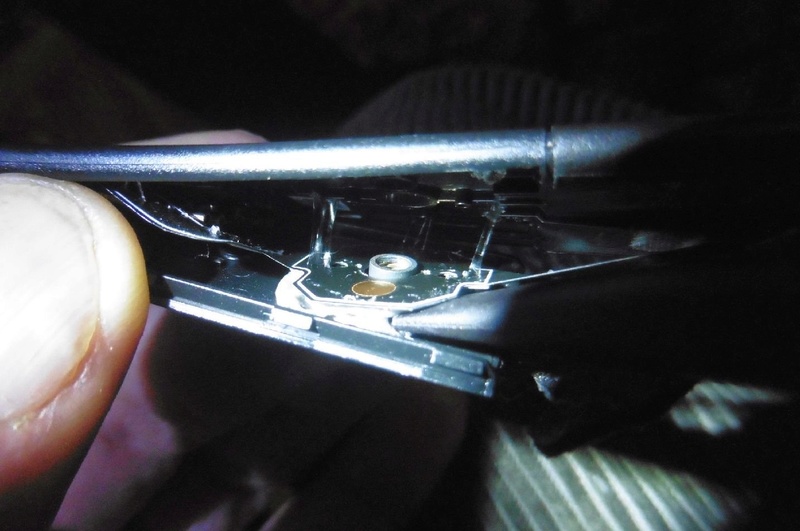
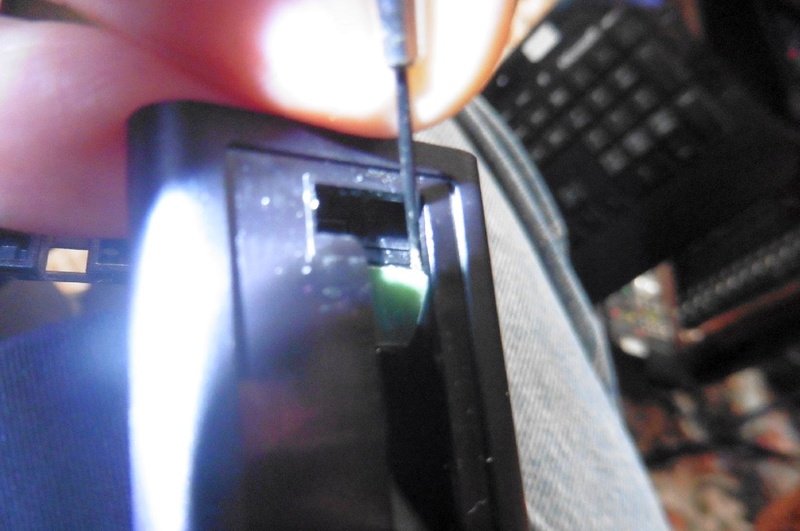
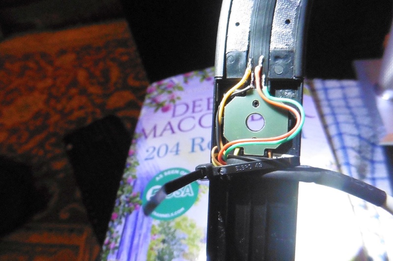
Further back just into the section that the headband slides into, there is a small square of printed board that the ribbon joins, it can be carefully lifted with a small screw drive under its top corner, see image.
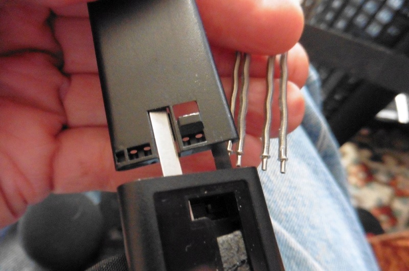
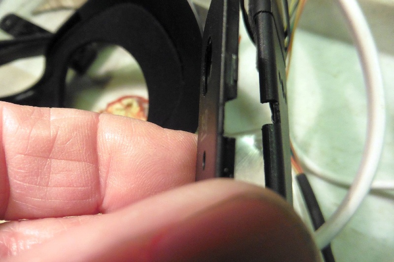
The new six way cable enters from the bottom through the side near the R/H earphone, by cutting a gap in the two sides, see image.
On the side of the large pad that the R/H earphone makes contact with, there are two copper pads, scrape toward the outside of the copper contacts to reveal more copper.
It is then simple to solder to this to feed audio to the R/H earphone.
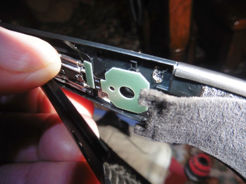
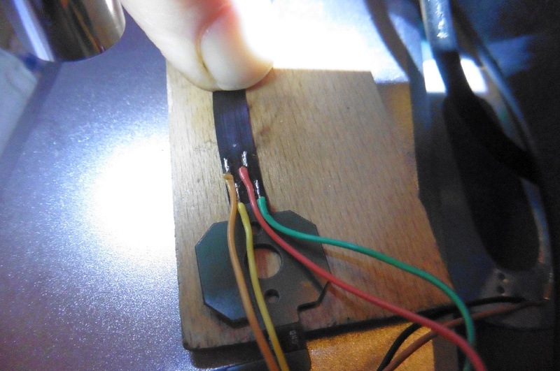
The remaining four wires can be soldered to the printed ribbon the at top side of the pad, see image.
First heave a small length of the inner cloth away from the inside of the headband to reveal enough of the print, see image.
The print is relatively large here as there are only four wires, two for the L/H earphone two for the LED's.
Down at the other end where you removed the velcro, cut the ribbon leaving an inch or so, if you leave the full section you will still have the part where the break is.
You could try to make the connection here, then pull the new six way cable back into the head set, this would mean soldering the other end later.
I think it is better to follow this link below and take the headset apart, it is not as bad as it may look.
This take apart or teardown as it is now called, is by another gentleman, it was to repair his motherboard, but will get you to the point of unpluging the cable for easy access : )
https://www.bing.com/videos/search?q=Oculus+Rift+CV1+Teardown+Disassembly+How+To+Part+1&docid=608048228884810647&mid=1520168C5E755E36FF431520168C5E755E36FF43&view=detail&FORM=VIREHT
Once you have done that you will have unplugged the ribbon cable and can work on connecting to it with more ease.
First you have to scrape a section of the coating off to reveal the printed tracks, then solder some fine cable, I think about .2mm diameter to the tracks.
Use a Stanley knife or sharp very small screw driver.
I used a camera microscope connected to a large screen via a laptop.
Or it should be possible with a very strong lenses, such as are sold on eBay for repairing watches.
Use a small soldering iron with a .2mm bit.
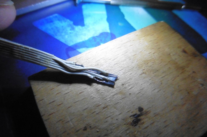
On my first repair I used six strands of computer ribbon cable to interface with the ribbon in the headset, then connected this to a six way cable to exit the headset.
It was on the large size and the outer insulation melted and looks a mess.
One wire came off in the first reassemble, but after fixing it it all works fine.
Checking the earphones are ok is by listening to them of course, the rear LEDs can be seen on a camera screen, with my camera I had to get very close and could just see them glowing.
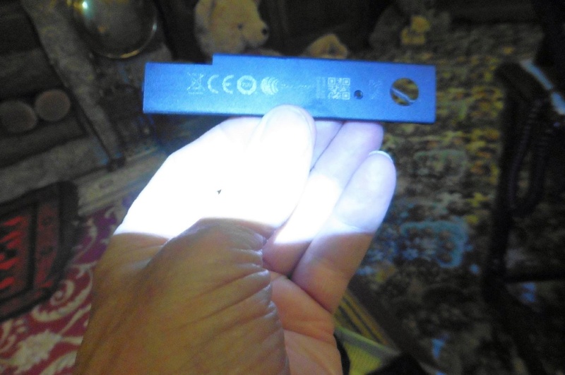
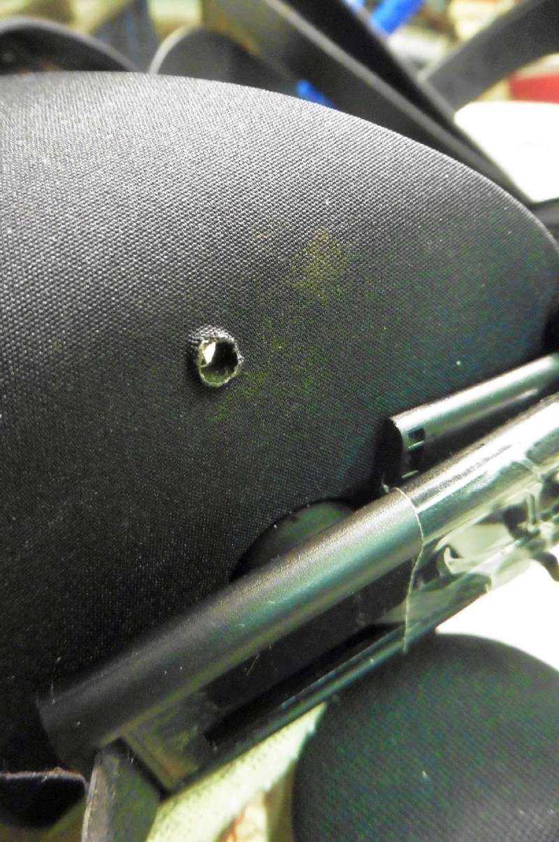
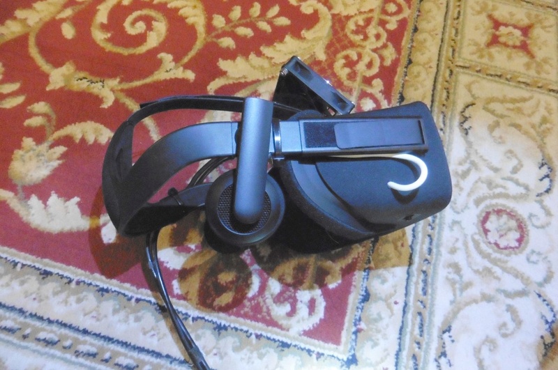
I cut a hole in the side of the headset for the new cable and used a cable clamp on a handy screw inside, see image.
I am going to redo the connection to the six wire section of the ribbon using fine transformer wire, ( suggested by my good friend Jack : ) scraping the shellac off a small section for the solder.
As with the ribbon cable I will then solder this to the six wire cable, insulate it with sleeving and tuck it inside the headset.
When soldering the print I used flux and tinned both the cable and the print, it is not easy but not that bad either.
I have been in electronics all my life and am now 72, so no problem for you youngsters : )
I will put up some more pictures after I redo it with transformer cable.
Just added an image of the headset end interface with the ribbon cable, this is the difficult end.
It shows just one wire connected at the moment to a test piece of ribbon cable.
The wire is very fine transformer wire, it looks large on the image but is very small perhaps .1 mm.
I think I shall leave the original repair as it is working : )
Good Luck God Bless Spiff
Just having a plug : ) Our website supplying service sheets and manuals for vintage radio, test equipment, miltary radio & amateur radio.
http://shopingathome.com/Military%20Wireless.htm


